
A failure-pattern guide for separating thermal stress, arc concentration, mechanical impact, connection and material evidence at a graphite electrode end.
Direct Answer
Tip splitting, surface spalling and end breakage are different failure patterns. Possible causes include localized arc heating, rapid thermal change, eccentric load, furnace contact or impact, pre-existing damage, joint or alignment problems, and material defects. Preserve the fracture pattern and event history before handling destroys evidence. Diagnose from location, surface, timeline and comparison pieces.
Key Takeaways
- Name the fracture pattern before proposing a cause.
- Thermal stress and mechanical impact can produce different but overlapping evidence.
- Joint location, arc position, furnace contact and handling history matter.
- Protect fracture surfaces and retain identifiable pieces where site safety permits.
- A supplier review needs batch and furnace evidence, not only a broken fragment.
Table of Contents
- Separate the failure patterns
- Preserve evidence safely
- Screen thermal, mechanical and connection causes
- Build a fracture timeline
- Correct and verify
Separate the Failure Patterns
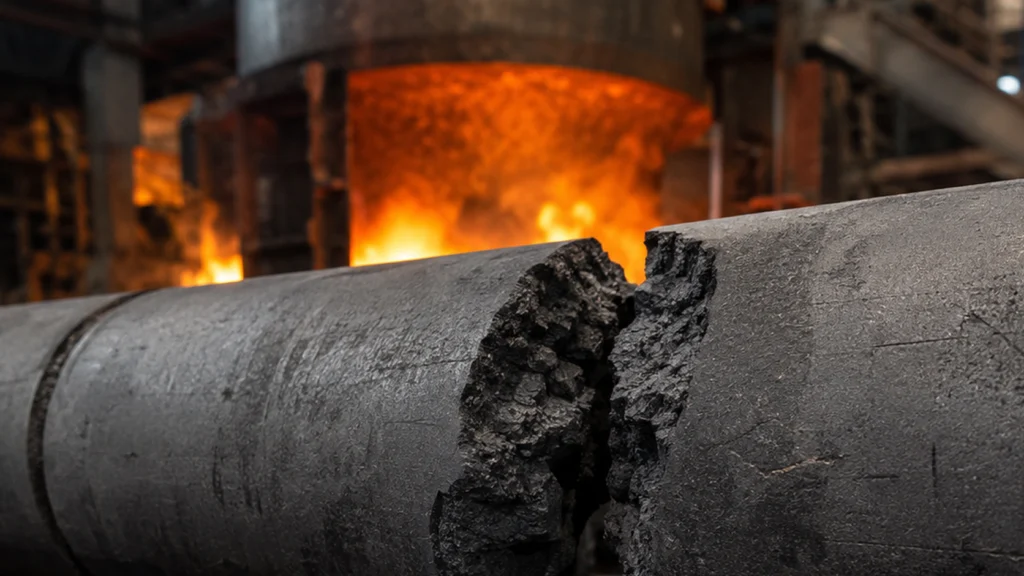
Tip splitting usually describes a crack that divides or opens the electrode near the working end. Spalling describes pieces separating from a surface. End breakage may involve a larger transverse or irregular fracture. These terms should be supported by photographs and fracture location rather than used interchangeably in a complaint.
Record whether the fracture is near the arc end, near a joint, along the body, or at a visible impact point. Note the fracture direction, surface appearance, branching, oxidation and any missing material. Do not clean or grind the surface before the review unless the investigation procedure requires it.
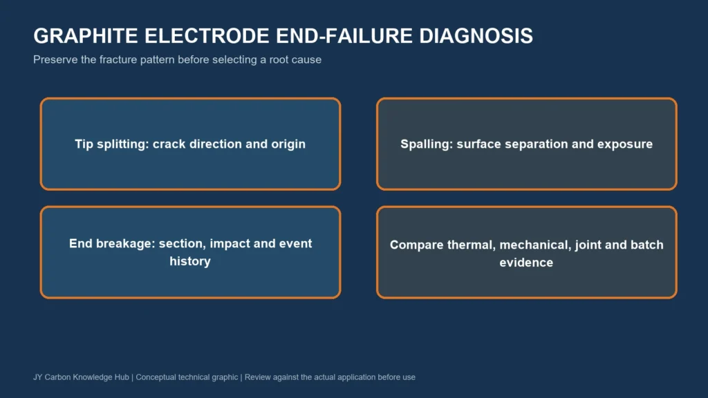
Failure-pattern guide. Similar appearances can have different initiating mechanisms.
Preserve Evidence Safely
First make the furnace and material safe under site procedures. Identify the electrode, batch, furnace position and event time. Photograph the installed condition from safe, authorized positions before pieces are moved. Label recovered pieces so their orientation and location remain known.
Record receiving and handling history, connection work, electrode additions, furnace events and previous visible damage. If the fragment cannot be retained, document dimensions and surfaces sufficiently for later comparison without delaying safe operations.
| Cause group | Evidence pattern to examine | Related records |
| Localized thermal stress | Crack origin near heated end, directional fracture or rapid event | Arc, power and furnace event history |
| Thermal cycling | Damage after shutdown, restart or sudden condition change | Operating timeline and exposure history |
| Mechanical contact or impact | Crush mark, chipped edge or fracture from a visible contact point | Handling, roof, scrap or furnace contact record |
| Joint or alignment | Fracture near connection, uneven face marks or column misalignment | Connection, tightening and alignment evidence |
| Material or prior defect | Repeatable internal feature or damage present before installation | Batch tests, receiving photos and comparison pieces |
Screen Thermal, Mechanical, and Connection Causes
Peer-reviewed work has analyzed graphite-electrode fracture produced by transient, localized end heating and the resulting thermal stress (thermal-stress fracture study). This supports thermal stress as one possible mechanism. It does not prove that every broken tip was caused by the arc or provide a universal operating limit.
Mechanical evidence may include impact marks, furnace contact, handling damage or obstruction. Connection evidence may include misalignment, damaged end faces, thread problems or uneven load transfer. Material evidence should be linked to batch records and comparison specimens, not inferred solely from fracture roughness.
Build a Fracture Timeline
- Receiving and pre-installation condition.
- Connection, handling and alignment events.
- Furnace position and operating phase at first observation.
- Arc, process, roof, scrap or equipment events near the failure time.
- Post-failure movement, recovery and evidence preservation.
The timeline helps distinguish damage that existed before installation from damage that developed during furnace use. It also reveals whether the fracture follows a batch, connection practice, furnace position or specific event.
Correct and Verify
Correct the confirmed mechanism under the site’s approved procedure. Handling or connection findings call for procedural and inspection controls. Furnace contact or thermal findings call for site engineering review. Suspected batch findings call for stock segregation, certificate review and material investigation.
After action, monitor whether the same pattern recurs under comparable conditions. Send the failure map, photographs, batch and connection records, and event timeline through the JY Carbon graphite electrode product page when supplier review is needed.
Sources
- Theory and Experiment of Thermal Stress Fracture of Graphite Electrodes for Steel-Making Arc Furnaces. Carbon, 1997. https://www.sciencedirect.com/science/article/pii/S0008622396001510
- An Analysis of Thermal Stress Fracture in a Graphite Electrode Used in an Arc Steel-Making Furnace. Carbon, 1974. https://www.sciencedirect.com/science/article/pii/0008622374900578
Written by Sterling Yang,Senior Vice President, Jincheng Jiyang Carbon Co.,Ltd.
Technically reviewed by Mr.Yang,Technical Director.


